- CYPE >
- english >
- faq >
- CYPE 3D >
- Comparison of results with CYPECAD and CYPE 3D
- > related programs
|
CYPECAD is a program conceived specifically to carry out the design and analysis of reinforced concrete, steel and timber structures, submitted to vertical and horizontal loads, for houses, dwellings and civil works projects. CYPE 3D is a generic program brought about to carry out the analysis of any type of bar structure composed of elements made up of steel, concrete or any other material. Therefore, the discretisations undertaken by CYPECAD and CYPE 3D are different:
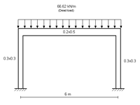
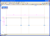
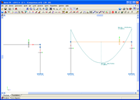
Nonetheless, by changing some options in CYPECAD and introducing elements in CYPE 3D to simulate the conditions of CYPECAD, it is possible for the results of a single spanning concrete frame to be the same in both programs. The following frame can be taken as an example:
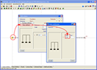
The same frame is introduced twice in the same job (one to the left and another to the right) in both CYPECAD and CYPE 3D.
i.e. The frame to the LEFT corresponds to CYPE 3D and the frame to the RIGHT corresponds to CYPECAD in both cases. Additionally, some of the column and beam options within CYPECAD have to be adjusted to be able to compare the results offered by both programs: 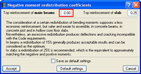

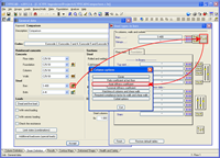
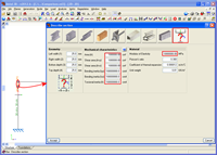
In CYPECAD the frame on the left is introduced in the usual manner (two columns and a beam without a floor slab, which implies the non-deformability of the floor has to be considered, i.e. 3 degrees of freedom) and for the left frame, the beam is introduced as a sloped beam that starts and ends at the same level. Sloped beams are not non-deformable in any plane and by using them the finite size of the nodes are not considered either (simulation of the analysis carried out by CYPE 3D: a beam with 6 degrees of freedom). The fixity coefficients of the last span of the columns have to be modified to reflect the pinned connection. A value of 1 represents a perfectly pinned connection. Due to reasons, which will be explained later on, the fixity coefficient of the last span of the columns of the left frame are to be changed to 0.96 and those to the right to 1.0: In CYPE 3D, the elements are represented by bars. Hence, to be able to compare the example with the CYPECAD model (frame to the left) the top beam has to be represented by its longitudinal axis. To represent the distance between the longitudinal axis of the beam and its base, an infinitely rigid bar has to be defined. The bar has to be described with the values shown in the image. This will make the bar extremely rigid but will not provide the perfectly pinned connection obtained in CYPECAD when the value of 1.0 is introduced as the fixity at the last span of the column, hence the reason for introducing a value of 0.96 to account for this.
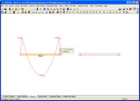
Ties in the Y direction (which corresponds to the introduction direction of the bar) are to be established between the end nodes, in order to simulate the rigid diaphragm. The ties at the end nodes of the beam cause the nodes to have the same displacement in the Y direction and as this example is symmetrical, it is as if the nodes do not move. RESULTSBelow are the results of this example. Having checked both programs, it can be observed that, thanks to the small modifications, the results are identical. Results of the left frame: In CYPECAD
In CYPE 3D
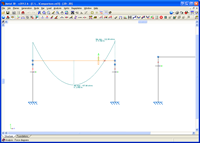
Results of the right frame: In CYPECAD
In CYPE 3D
ConclusionAs can be observed, the results obtained in both programs are practically identical. This confirms that, by using the adopted loadcases and introducing the adequate model, both programs provide the same results. |
Tel. USA (+1) 202 569 8902 // UK (+44) 20 3608 1448 // Spain (+34) 965 922 550 - Fax (+34) 965 124 950