- CYPE >
- english >
- faq >
- CYPECAD >
- Seismic load
- > related programs
|
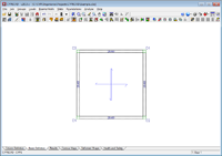
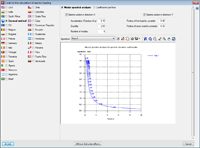
If we consult the CYPECAD's Calculation manual, the following text can be seen in the chapter corresponding to the analysis with seismic loading: ...Depending on the selected earthquake code of each country, it is compared with the minimum eccentricity specified in each code and if less, the rotational mode is amplified, in such a way that at least the minimum eccentricity is obtained. If the earthquake loads on the structure are analysed in a generic manner (Modal spectral analysis), the minimum eccentricity the program takes into account is 0.05. This is important especially in the case of symmetrical structures. We can use a simple example to verify that a minimum eccentricity of 5% has been considered, with respect to the dimension that is orthogonal to the seismic direction that has been considered, upon applying seismic loading using the modal spectral analysis. First of all, we shall introduce a simple model consisting of four columns, which support a 6 x 6 m flat slab. We then apply the seismic action by selecting the modal spectral analysis, as indicated in the figure. Once the analysis has been carried out, open the “Justification of seismic action report". Here it can be seen that the rotational mode (mode 3) does not move any mass because of the symmetry. Additionally, mode 1 moves all the mass in the x-direction, and its unit movement components (Lx = 1, Ly = 0, Lgz = 0) are all movements in the direction of the x-axis. The same occurs with mode 2 in the y-direction.
From the results that have been obtained, we can deduce that no torsion should appear in the building, except if an additional eccentricity is applied. Using the report summarising the sum of the forces in reference to the coordinate origin, we can obtain the information we need to verify that an additional eccentricity of 5% has been applied.
Bear in mind that the centre of mass of the structure is located at coordinates (x = 7m, y = 7m). For seismic loading in X, mode 1: We can verify the torsional force is practically non-existent, by moving the forces due to the seismic loading in X, of mode 1, to the centre of mass.
...The value of 0,3 kNm is due to rounding of the values. When the column forces are consulted on screen, it can be seen that the values displayed are more precise due to a higher number of decimal places.
For seismic loading in Y, mode 2: The operation is identical to that above.
For seismic loading in X, mode 3: Here is where the program should apply the 5% eccentricity. The total torsional force with respect to the centre of mass is the same as that displayed by the program with respect to the origin, because the total shear force is null.
The total torsional force could be substituted by an equivalent force system composed of a shear force applied at a point at a distance from the centre of mass. If we take the maximum shear force from all the modes, a value of 52,1 kN is obtained, and therefore an eccentricity of:
If we then divide by the total length:
We obtain the 5% of the total length. Obviously, the same eccentricity is applied in the other direction. To summarise, even though the analysis is carried out based on the displacements, and not the forces, it can be deduced, approximately, that if torsional forces are not obtained due to symmetry, a rotational mode is applied until forces equivalent to applying a shear force with a 5% eccentricity with respect to the centre of mass are reached. If the building has two floors and six vibration modes are analysed, the minimum eccentricity will be applied on the rotational mode with greatest period, as can be seen in the following table, which has been obtained upon adding an extra floor level to the example. In this case the rotational modes are the second and sixth modes.
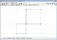
Additionally, if we modify one of the two dimensions (for example in the x-direction) and we change it from six to four metres, we can see the differences in the applied eccentricities. In this case, the rotational modes are once again the second and sixth modes.
For seismic loading in the x-direction:
For seismic loading in the y-direction:
|
|||||||||||||||||||||||||||||||||||||||||||||||||||||||||||||||||||||||||||||||||||||||||||||||||||
Tel. USA (+1) 202 569 8902 // UK (+44) 20 3608 1448 // Spain (+34) 965 922 550 - Fax (+34) 965 124 950


