- CYPE >
- english >
- faq >
- CYPECAD >
- deflection between 2 points
- > related programs
|
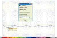
Upon marking an initial and final point on the plan view of a flat or waffle slab, a continuous yellow line appears joining the two points displaying the vertical displacements of all the points creating an approximately sinuous curve below the line. The blue curve displays the deformed shape of the slab, for a simple loadcase, combination or worst case combination (G+Q) with amplified displacements. When the floor layout of the supports is visible on screen and the two points
to calculate the deflection are marked, the user can observe that convex distributions
are present in the support zones whereas at span centres concave distributions
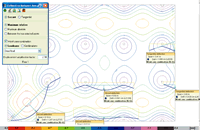
are visible. In the case of a two-way spanning slab, we do not know beforehand whether the area with greatest concave distribution corresponds to that of themaximum absolute deflection. It is logical to think it should be, as the descent of the supports is generally small, and we should concentrate on those areas where these maximum values can be seen. There is also the uncertainty as to in which direction (X, Y, diagonal) the points should be marked to obtain the maximum relative deflection. However, one could say, from observing the layout of a floor, that it should be in the direction of the smallest distance between two points of the concave distribution perimeter. It is recommended it generally be done in this manner. To find the edges of the concave distribution perimeters, it may be useful to previously select points which lie further away so to find their position. Let us carry out a few simple examples so to clarify what has been explained. The data is as follows:
Negative moment internal support
Let us estimate a depth of 26 cm, whose slenderness is L/h = 650/26 = 25, Its deflection has to be checked. According to table 50.2.2.1.a of the Spanish EHE-08 code, the value for the slenderness is 23 (for weakly reinforced elements) and so its verification must be justified. Let us carry out an approximate analysis on a metre wide section, with the aforementioned properties and to obtain the forces acting on it. Even though the support distribution is that of a flat slab with isolated supports, we shall assume there are uniform supports so to simplify the analysis. The gross inertia of the section of the flat slab is To establish the deflection between two points based on the displacements, the displacements of the initial and final points must be deducted. The graph shows a line which passes through those two points (secant) or a line at a tangent to the initial point (tangential), depending on the section carried out. The deflection is measured with respect to that line. The values displayed are:
A “Displacement amplification factor” = 2.50 (default value) is displayed. This does exactly as it says; multiplies the displacements due to that loadcase by that value and displays the result. This amplification factor should be incorporated and all the parameters relative to the following be taken into account:
Once the instantaneous elastic deflection is known, the total deflection or active deflection (after the damageable elements have been built, for example partitions or rigid paving without joints) can be found, by estimating the aforementioned parameters. By placing the adequate value, the deflection sought will be obtained and so can be compared with the limits stated in the code. Assuming a usual construction process, with the corresponding building loads:
Using the laws applicable to an external span (as if virtual frames were to be applied), the bending moment diagram and the required reinforcement per metre width can be found. Hence providing an approximate area, Now to calculate the cracking moment: Where fct,m,fl: mean tensile bending resistance of the concrete An added safety factor is applied by considering the service moments due to the total load: To determine the cracked inertia Icrack y and Branson’s equivalent inertia Ie : where: This is done in the 3 sections under study:
And the mean equivalent inertia of the span will be determined :
To be on the safe side and by reducing the equivalent inertia to If the method described in the Spanish EHE-08 code (similar to ACI-08), where the differed deflection is assumed to be proportional to the instantaneous deflection by a factor λ whose value is: ξ: coefficient which depends on the time or duration of the load If a top and bottom mesh is provided which will cover, for example 1‰ (ρ = 0,001), ξ will take the following values:
Let us now look at the construction process and the deflections that are produced. First of all, assume the total deflection:
With the assumed live load, only the quasi-permanent part produces differed deflection (for dwellings Y2=0,3). By applying it to the total:
To obtain the instantaneous deflection corrected by the reduction of the inertia due to cracking, the value of the instantaneous deflection δi is multiplied by Ke:
On the other hand, for the total differed deflection a coefficient of λ = 1,00 has been obtained, hence
and the total deflection is:
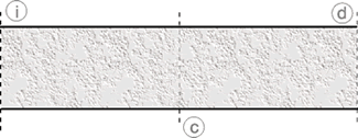
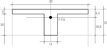
This value of 3,00 is precisely that coefficient which is presented as “Displacement amplification factor” (whose default value is set at 2,5) CYPECAD’s user’s manual mentions that this value can lie between 2,5 and 3,0, depending on the construction process. For this example the value obtained has been 3,00, amount which is to be introduced in the dialogue box to consult the total deflection and view the selected results between two points. Similarly, to determine the active deflection, in this case, that which arises after the damageable element has been built, the deflection which occurs before it is built must be subtracted. In this example, the instantaneous deflection due to the self weight of the slab and the differed deflection since removing the props until the partitions were built after 60 days have to be removed. Hence ξs.weight = (2- 0,8) = 1,2, and so: Therefore the differed deflection will be δdif = 0,93 δinst. Regarding the instantaneous deflection to be considered, the corresponding part due to the self weight must be removed. Hence by the proportion of the loads without the self weight to the total loads: Therefore: This would be the value to introduce in the “Displacement amplification factor” box to obtain the active deflection. Obviously, it can be seen that for the foreseen loads and construction periods, by rounding off to whole values, a flat slab has an active deflection of approximately 2,0 times the instantaneous elastic deflection established using the gross section and a total deflection of approximately 3,0 times that instantaneous deflection. 2nd case: Waffle slab with lost forms A similar estimate will now be undertaken for a waffle slab introduced in CYPECAD. The lost form waffle slab for this example will have the following geometry: Having found the centre of gravity of the section, the inertia of the gross section with respect to this centre of gravity can be calculated: By repeating the same process with the drop panel zone, it can be seen that it resembles a flat slab with a depth of 30 cm and a width of 82 cm: The mean inertia of the section along its span could be estimated to be: In the CYPECAD model, the inertia applied to all the mesh of a panel of any waffle slab, be it in the lightweight or solid zone, is the same and is taken as half of that of the solid zone, which in this case is: and it is with this inertia that the elastic displacements for each loadcase are found. For the solid zone and taking a width = 0,82 m, the cracking moment is: and for the lightweight zone: Let us estimate the moments acting on the structure:
The moments for hypothetically supported rib would be: It can be seen that there is very little cracking in the negative moment zones, however there is in the positive moment zone of the span. The equivalent inertia of the span can be estimated as: For the right support, it shall be taken equal to the gross section: and for the left support: By taking the average: As the inertia considered in the analysis Regarding It can be said that the differed deflection is approximately equal to the instantaneous deflection (δdif ≈δinst = 1,25 fδ); and the total deflection is:
Now to obtain the differed deflection after the partitions have been built: and the instantaneous deflection must be left without the self weight of the slab: hence the active deflection will be: It can be said that the total long-term deflection for a waffle slab must be obtained with a displacement amplification factor of the order of 2,5 times the instantaneous elastic deflection of the program, and for the active deflection, the user would have to multiply the instantaneous elastic deflection by 1,75. It must be taken into account that the indicated coefficients are those applied to usual building cases such as those mentioned regarding, span lengths, depths, loads, construction procedure, normal environment conditions, unpropping periods, and entering into force of the loads in time. If these conditions are varied, then logically the pertinent correction coefficients have to be applied. If the deflection to be verified is that for comfort, it will be sufficient if the deflection due to the live loads in loadcase LL are analysed.
SUMMARY TABLE
|
Tel. USA (+1) 202 569 8902 // UK (+44) 20 3608 1448 // Spain (+34) 965 922 550 - Fax (+34) 965 124 950


