- CYPE >
- english >
- faq >
- CYPE 3D>
- Data introduction
- > related programs
|
Surface loads are introduced in the same way in CYPE 3D and Integrated 3D structures of CYPECAD. To be able to introduce surface loads in CYPE 3D or in the Integrated 3D structures of CYPECAD, the user must first define a panel on which the loads can be applied on all its surface or in specific zones of the panel’s surface. The loads applied to all the surface of the panel are introduced when the panel is defined. The user has a set of tools for the definition and edition of these loads and panels and are located in the Load menu. These are:
The user has a set of tools for the introduction and edition of surface loads applied to specific areas of the surface of the panel. These are located in the Load menu and are:
There is one further option regarding panel surface loads and surface loads defined on zones of a panel:
There are also two dialogue boxes, which appear when panels and surface loads are introduced, whose properties should be known:
Options of the Load menu to manage panels and surface loads The options mentioned in the Load menu are detailed below: Introduce panels: Introduces a panel formed by a closed polygon that can have loads applied on all its surface, or alternatively, surface loads applied on certain areas of the panel. The user must indicate the direction of the one-way distribution that both the load of the panel and the surface loads it contains will have. For example, on the roof of a warehouse, the direction applies to the purlins, if what is to be loaded are the transverse frames. Edit loads on panels: Allows to modify the list of loads applied to selected panels. If the panel is not parallel to the global XY plane, the dialogue displays two tabs: one for uniform loads and the other for loads that vary in height, whilst in the case of horizontal panels, only the list of uniform loads is displayed. The program applies the criteria that all the loads except wind loads act in a positive downward direction (in the direction of the negative Z axis) without taking into account the vector of the positive load. The wind loads, however, are considered to act perpendicularly to the panel bearing in mind the direction of the positive load vector. Loads are introduced with their respective positive or negative sign. This tool also allows for loads to be matched if a multiple panel selection has been carried out. Modify the distribution direction of the loads: Using this option it is possible to modify the distribution direction of the loads on a panel. Once the panel has been chosen, in order to indicate the new direction, one of the auxiliary straight lines defining the sides of the panel must be selected. Delete panels: Deletes the selected panels, and therefore, their associated surface loads. Introduce surface loads: This option allows to introduce a surface load with a polygonal shape. Loads can be uniform or vary depending on the height if the surface is not horizontal This surface distributes the loads depending on the direction of the panel to which it belongs. A surface load belongs to a panel in which it is completely contained, and so it is not permitted for a load to overlap with more than one panel. An example of surface load application can be the loading of a panel with different wind pressures. Upon introducing a new surface load, the program detects if it overlaps with an existing panel. If it does not, the user is asked whether or not a distribution panel is to be generated in the same way as the created surface. This new panel has a distribution direction given by the straight line joining the first two points of the introduction of the surface, even though this direction can be modified later with the option 'Modify the distribution direction of the loads'. Edit surface loads: Modifies one or several surface loads belonging to the currently viewed loadcase. Only loads associated with the 'visible loadcase' are displayed on screen. Copy surface loads: Using this option a new surface load is created based on the data of an already existing load. The new surface load has the same shape and position as the existing load and so the user only has to indicate the loadcase and the load values. Delete surface loads: Deletes the selected surface loads amongst those corresponding to the 'visible loadcase'. Activate/deactivate surface load assignment: Indicates if one or several bars can be loaded by panels or surface loads. If a bar is deactivated, it will not accept loads in any loadcase. This option has no effect on tie rods, as loads cannot be applied on them; they are always deactivated. Loads on panel dialogue box: The Loads on panel dialogue box appears when the Introduce panels option (after geometrically defining the panel and indicating the distribution direction of the loads) or Edit loads on panel (after selecting the panel containing the loads) is selected. 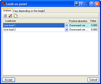
Within this dialogue, if the selected panel is horizontal (parallel to the global XY plane) only uniform loads can be applied, whilst if it is not, two tabs appear: one to manage the list of uniform loads and the other for loads that vary with height. It is possible to add an unlimited number of loads for each type in one or various loadcases. In uniform loads it is sufficient to indicate the value and sign for each of them, whilst for those variable with height, it will be necessary to indicate the bottom Z coordinate and top Z coordinate of the panel. The data of column 'Positive direction' is not editable; it is merely informative, by means of texts 'Downward vertical', 'Upward vertical' or the coordinates of a unit vector that represents the direction of a positive load. Remember that in the case of different wind loadcases, a load is positive if its vertical direction is downwards, regardless of the direction of the aforementioned vector. However, for wind loadcases, the defined loads refer to the mentioned vector. The format of the load list in panels helps with data introduction and revision. Additionally, using the ‘Edit loads on panels’ option it is possible to rapidly assign the loads from one panel to another. Introduce surface loads dialogue box When the Introduce surface loads, Edit surface loads or Copy surface loads options are used, the following dialogue box appears. 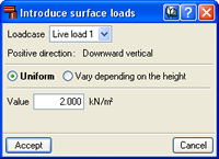
Surface load edition is done by loadcase, in other words, a load is applied in a single loadcase. Upon selecting this option, only surface loads belonging to the selected 'visible loadcase' are displayed on screen. If the loadcase to which the load belongs to is modified, this will become hidden if it is not found in the current 'visible loadcase'. In the same way as loads on panels, surface loads can be uniform or vary with height. It is sufficient to indicate the value and sign of the load for uniform loads, whilst for loads that vary with height, it will be necessary to indicate the values and signs of the loads at the bottom and top Z coordinates of the loaded surface. The positive direction of the load is given in the dialogue by means of the texts 'Downward vertical', 'Upward vertical' or the coordinates of a unit vector, in order to introduce the correct sign of the load. Remember that in the case of different wind loadcases, a load is positive if its vertical direction is downwards, regardless of the direction of the aforementioned vector. However, for wind loadcases, the defined loads refer to the mentioned vector. |
Tel. USA (+1) 202 569 8902 // UK (+44) 20 3608 1448 // Spain (+34) 965 922 550 - Fax (+34) 965 124 950